")
")
Delta SmartWave – Installation Guide
This tutorial will guide you step by step through the installation of the Delta SmartWave inside your Sony PlayStation 1 PS1. SmartWave automatically fixes frequency (50/60 Hz) and video subcarrier issues to achieve a correct, clean, and stable image on Freezone consoles equipped with a modchip or an ODE such as XStation, DeltaStation, or PicoStation.
Fixes black-and-white image issues with imported games, restoring full color output.
Automatically fix 50/60 Hz + video subcarrier on consoles equipped with an ODE or a modchip.
Identify your Playstation PS1 motherboard (PU-7 → PU-23) before installation.
• Press Power (while unplugged) to help discharge residual power.
• Wait ~2 hours (minimum) for capacitors to discharge.
• Never work on the console while powered.
• Do not disassemble / handle the internal power supply.
✨ Features – Why Delta SmartWave?
- Automatically detects PAL 50Hz or NTSC 60Hz
- Adjusts GPU frequency and the video subcarrier
- Eliminates black & white image issues (composite)
- Ultra-precise frequency generator
- Aligned with original PAL/NTSC specifications
- Excellent results for OSSC, capture, and purists
- Smarter than MFO / MOFO and DFO
- No programming, no surprises
- Compatible with all PlayStation versions (PU-7 and PU-8 EARLY included)
🧰 Required tools
- Delta SmartWave
- Phillips screwdriver
- Soldering iron (fine tip recommended)
- Solder (electronics grade)
- (Recommended) Flux + magnifier / microscope
🧩 Compatibility PS1
🌍 PlayStation FAT compatibility (models)
✅ 1 - Identify your PlayStation console
Check the label under your console and note the model (e.g. SCPH-7502). This is useful, but to choose the correct procedure you must confirm the motherboard revision (PU-7 → PU-23).
🔧 2 - Disassemble the PlayStation console
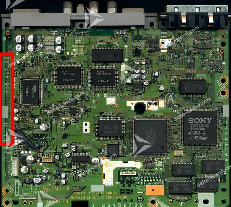
🧭 3 - Identify your motherboard (PU)
Identify your motherboard using the photos below. This step is essential because solder points vary depending on the revision.
🧩 4 - Delta SmartWave installation (by motherboard)
4.4.2 – Remove the resistor circled in red (top side):
4.4.5 – Reassemble your console.
4.5.2 – Remove the two resistors circled in red:
4.5.5 – Reassemble your console.
4.6.2 – Remove the two resistors circled in red:

Introduction
This topic aims to guide you through the installation of the chip "Delta SmartWave" in your Sony PlayStation 1 console.
Features
The Delta SmartWave allows your console to automatically adapt to the GPU frequency and video subcarrier based on the region of the inserted game (50Hz or 60Hz).
If you try to play an imported game (e.g., JAP) on a European (PAL) console, you may end up with a black and white screen. This is due to the incorrect timing required by the game compared to what is present in your console.
A 60Hz game (JAP or USA) should normally be played on an NTSC console.
A 50Hz game (PAL) should normally be played on a PAL console.
Thanks to the Delta PSNee (available at the
However, the console's frequency is not modified, which results in black and white images.
Some people use an RGB cable to improve the quality of the video signal.
The RGB cable will return color to your games, but will hide the frequency issue. For purists and OSSC owners, it is essential to correct this.
That's where Delta SmartWave comes in!
Through intelligent detection, the Delta SmartWave automatically adjusts the GPU frequency and video subcarrier with great precision, correcting all the previously mentioned issues.
With the combination of "Delta PSNee" + "Delta SmartWave," you will have the ultimate console—no need to own three different consoles for each region (PAL, JAP, USA).
Finally, we remind you that Delta SmartWave was designed to be soldered without cables!
Delta SmartWave est plus precise et plus intelligente que :
- PS1 MFO / MOFO (Multi Output Frequency Oscillator)
- PS1 DFO (DUAL Output Frequency Oscillator)
No need for programming or unpleasant surprises like the mods mentioned above!
Delta SmartWave is an intelligent solution that adapts to all situations, without asking any questions
Delta SmartWave: A Major Advancement Over Traditional DFO (Dual Frequency Oscillator) and MFO (Multi Frequency Oscillator)
1. An Intelligent Microcontroller for Precise Adjustments
As the name suggests, the SmartWave is “smart.” It features a microcontroller capable of automatically detecting the console version (PU-7, PU-8 early, PU-8 late, PU-18, etc.) on which it is installed. This allows it to precisely adjust its frequencies to match the technical specifications of each model, unlike DFO/MFO, which do not cover all variants, such as the PU-7 and PU-8 early.
2. Universal and Automatic Compatibility
Frequency management varies between PlayStation versions. While DFO/MFO often require modifications or are incompatible with certain models, the SmartWave automatically detects the region and console characteristics, adjusting to the correct frequency (PAL 50Hz or NTSC 60Hz) without manual intervention.
3. An Ultra-Precise Frequency Generator
The SmartWave integrates the most precise frequency generator available to date, ensuring perfectly aligned frequencies with the original specifications of PAL and NTSC consoles. By comparison, DFO/MFO use approximate frequencies, often with high decimal values. While functional, they are significantly less optimized.
4. Easy Installation and Optimized Performance
Unlike DFO/MFO, which may require complex manual configurations, the SmartWave is easy to install, without additional wiring (*one wire required for PU-7 and PU-8 EARLY). Once in place, it operates autonomously, offering unmatched precision and eliminating video synchronization issues or black-and-white display problems.
The Issue of Regional Frequencies
When a PAL PlayStation is used with an NTSC-J or NTSC-U/C game and the original composite video cable, the display appears in black and white.
An RGB cable can restore color, but this only solves part of the problem…
The real issue lies within the GPU (Graphics Processing Unit) and the video subcarrier:
1. The console’s GPU is clocked differently depending on the PlayStation’s original region.
2. PlayStations use region-specific crystals (PAL or NTSC), which can lead to underclocking or overclocking depending on the game being played.
This discrepancy, while subtle, is noticeable:
• The GPU and other components do not operate at their optimal frequencies.
• This can cause slowdowns or a loss of fluidity in certain games.
Why Delta SmartWave is Different ?
Delta SmartWave directly adjusts the GPU clock frequencies and the video subcarrier.
Thanks to its intelligent management system:
• It automatically detects whether the game is PAL or NTSC and adjusts frequencies accordingly.
• It restores perfectly aligned frequencies (PAL 50Hz or NTSC 60Hz), eliminating any underclocking or overclocking.
In Summary
Delta SmartWave vastly outperforms DFO and MFO in terms of precision, compatibility, and intelligent frequency adjustment. It offers an innovative plug-and-play solution that adheres to the original console specifications, delivering an unmatched retro gaming experience.
- Compatible with all PlayStation versions :
| SCPH-1002 SCPH-5502 SCPH-5552 SCPH-7002 SCPH-7502 SCPH-9002 |
SCPH-1001 SCPH-5001 SCPH-5501 SCPH-7001 SCPH-7501 SCPH-9001 |
SCPH-1000 SCPH-3000 SCPH-3500 SCPH-5000 SCPH-5500 SCPH-7000 SCPH-7000W SCPH-7500 SCPH-9000 |
SCPH-5503 |

- Delta SmartWave
 Delta Store >>
• A Phillips screwdriver
• A soldering iron
• Solder
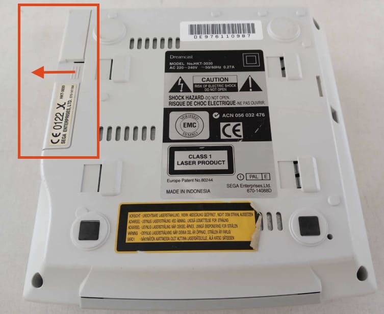
1 - Identification of your PlayStation console
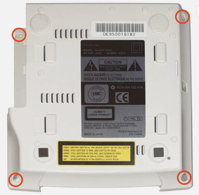
First, locate the label underneath your PlayStation console.
On this label, identify the model of your PlayStation.
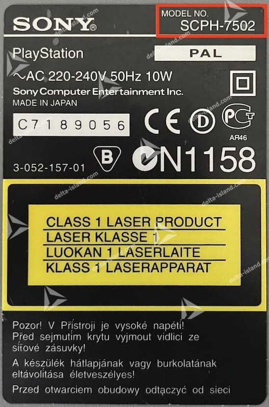
In this example, the model is “SCPH-7502”. While this reference provides important information, we need to verify the exact motherboard revision.
To do this, we will need to access your console’s motherboard.
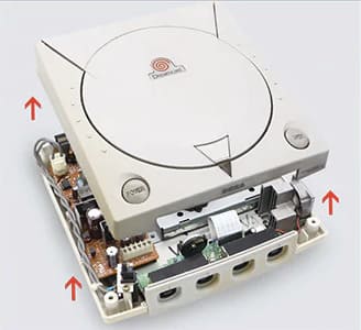
2 - Disassembly of the PlayStation console
Below, you will find various videos.
The goal is to access the motherboard. You do not need to disassemble the console’s power supply. Please do not touch it!
3 - Identification of your PlayStation motherboard
Please identify your motherboard using the following photos :
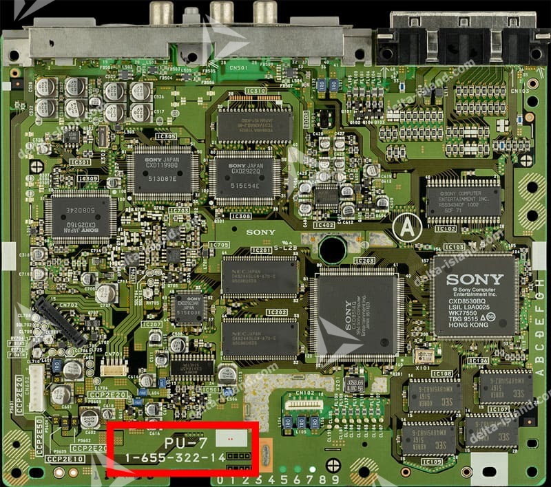 |
PU-7 // 1-655-322-11 PU-7 // 1-655-322-13 PU-7 // 1-655-322-13A PU-7 // 1-655-322-14 PU-7 // 1-655-322-14A PU-7 // 1-655-322-15 PU-7 // 1-655-322-16 |
 |
PU-8 // 1-658-467-11 PU-8 // 1-658-467-12 PU-8 // 1-658-467-13 |
 |
PU-8 // 1-658-467-21 PU-8 // 1-658-467-22 PU-8 // 1-658-467-23 PU-8 // 1-658-467-41 PU-8 // 1-658-467-42 |
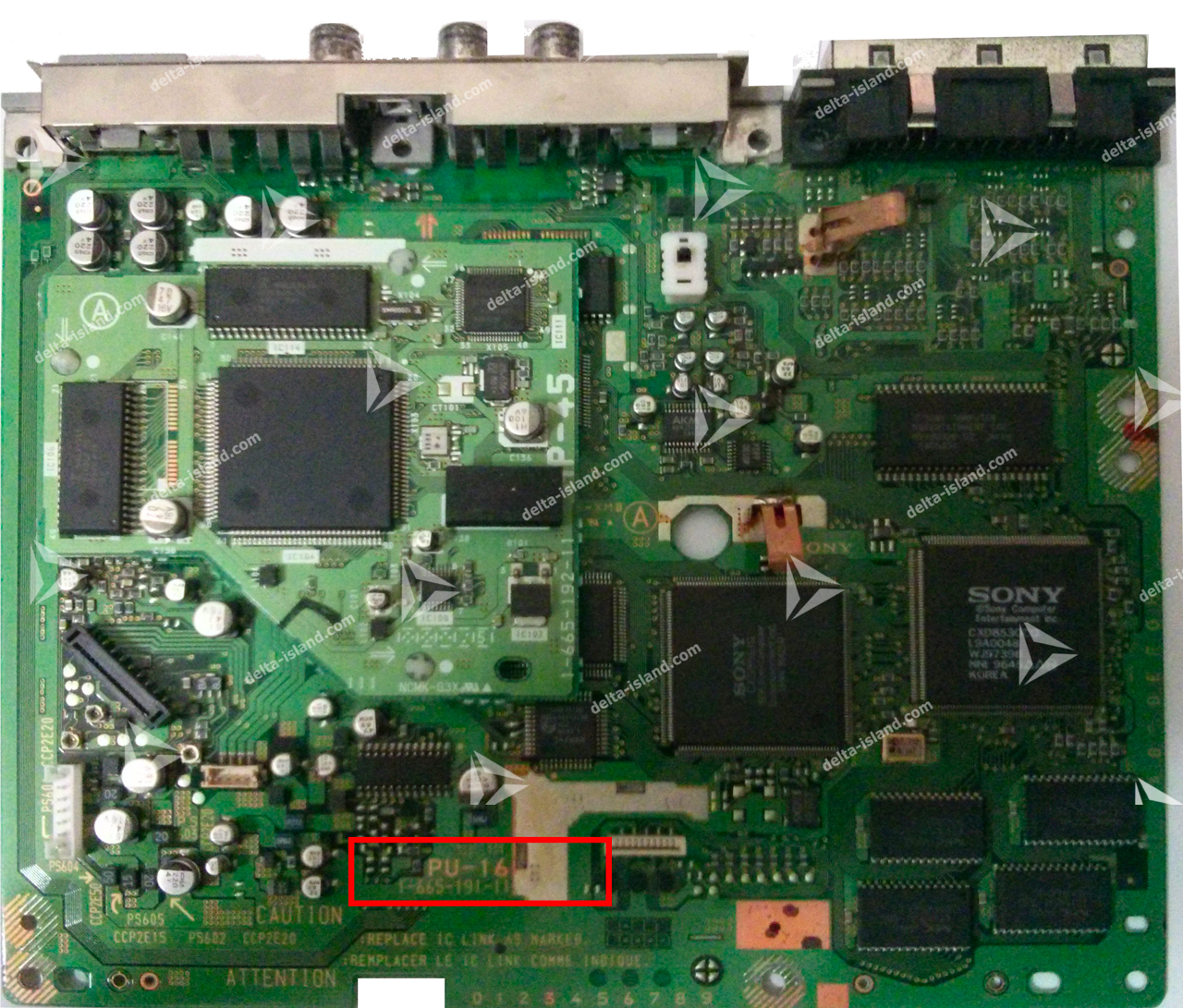 |
PU-16 // 1-665-191-11 |
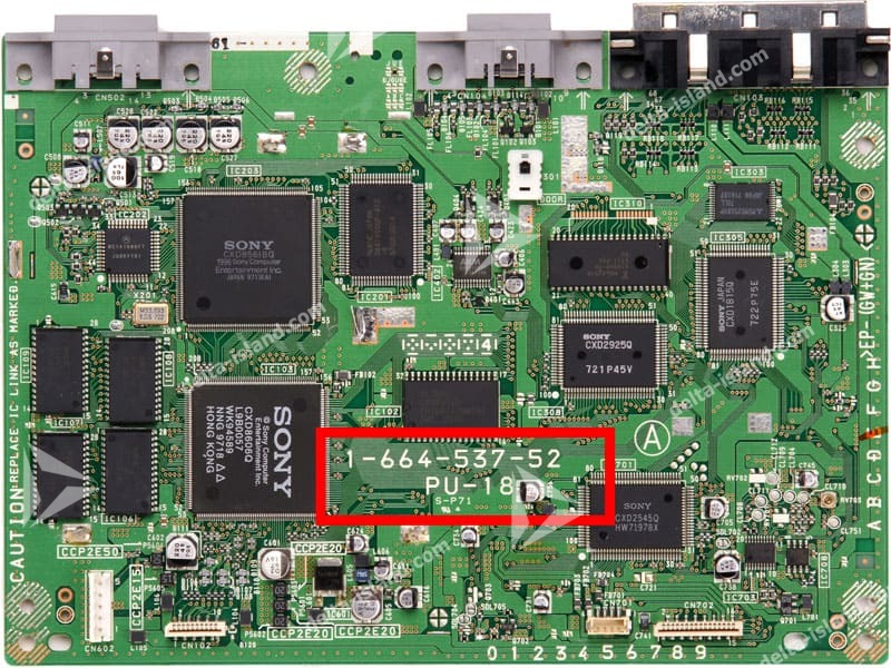 |
PU-18 // 1-664-537-11 PU-18 // 1-664-537-21 PU-18 // 1-664-537-31 PU-18 // 1-664-537-41 PU-18 // 1-664-537-52 PU-18 // 1-664-537-62 PU-18 // 1-664-537-72 PU-18 // 1-664-537-82 |
 |
PU-20 // 1-668-413-12 PU-20 // 1-668-413-22 PU-20 // 1-668-413-32 PU-20 // 1-668-413-42 |
 |
PU-22 // 1-671-858-11 PU-22 // 1-671-858-12 PU-22 // 1-671-858-21 PU-22 // 1-671-858-22 PU-22 // 1-671-858-32 |
 |
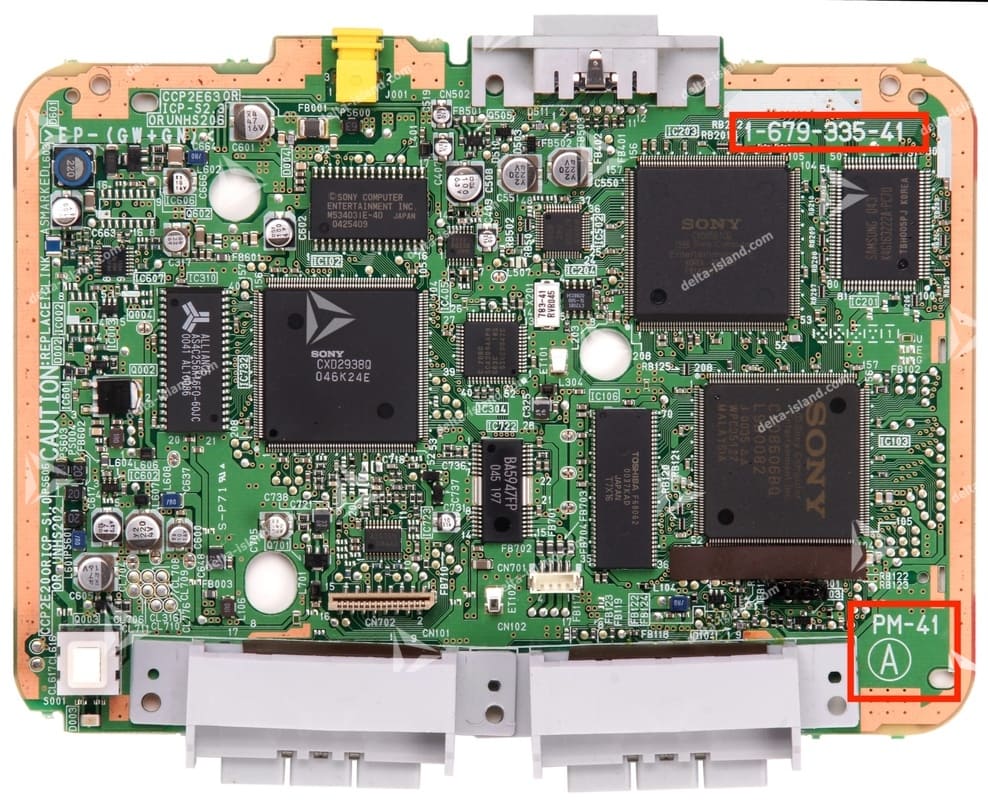
PU-23 // 1-674-987-11 PU-23 // 1-674-987-21 PU-23 // 1-674-987-31 PU-23 // 1-674-987-41 PU-23 // 1-674-987-51 |
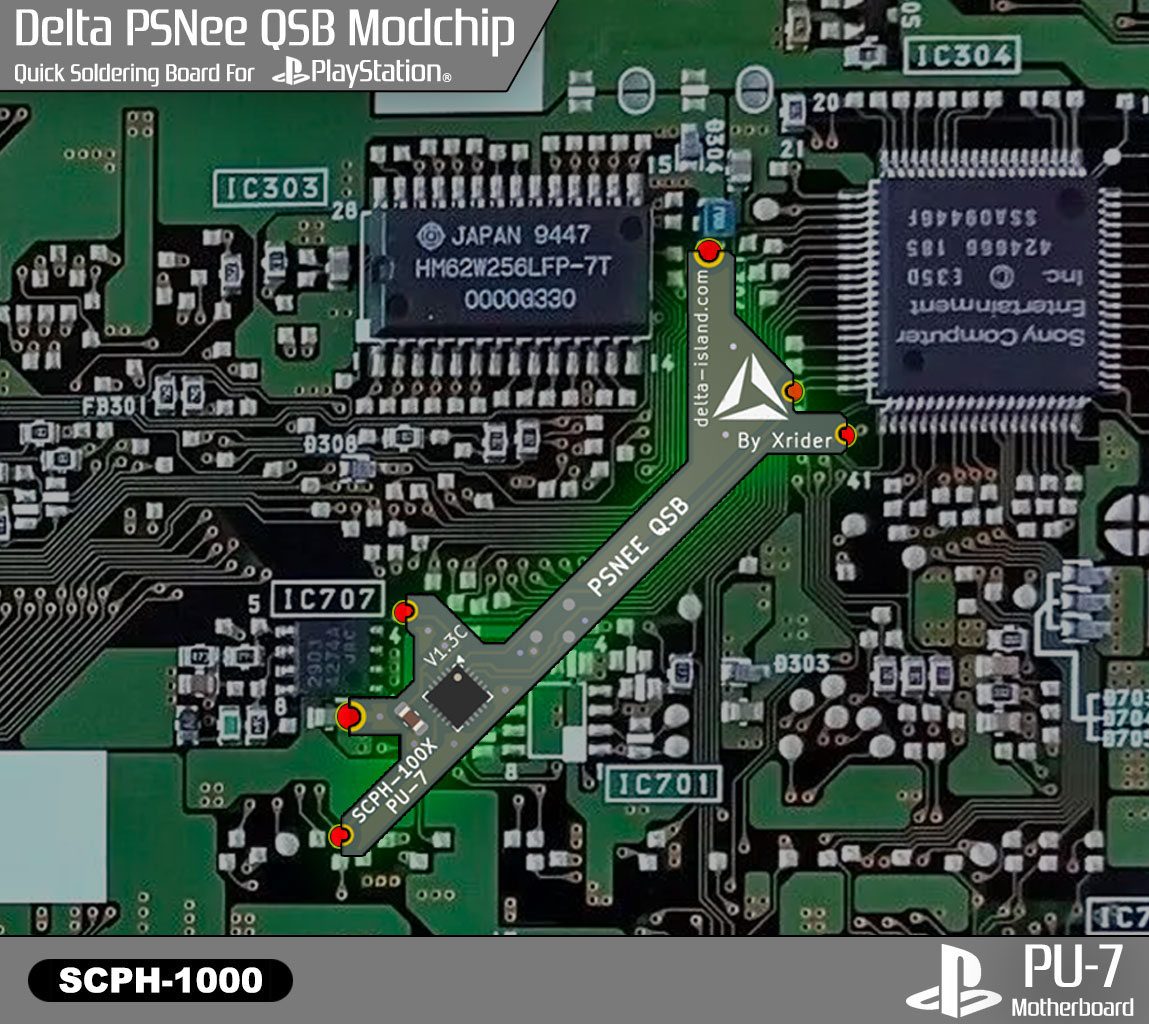
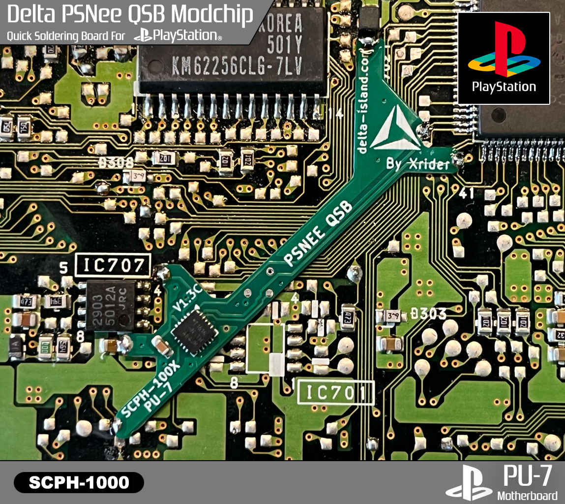
4.1 - PU-7 Mainboard
4.1.1 - Locate the resistors marked in red and remove them (top side).
Please note that depending on your motherboard version, you should have only one of the two resistors marked in red on the left.

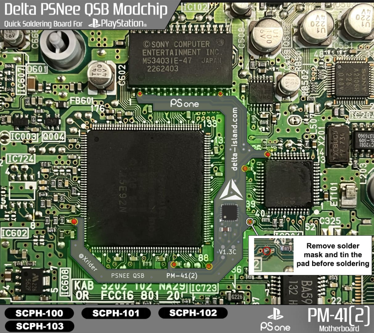
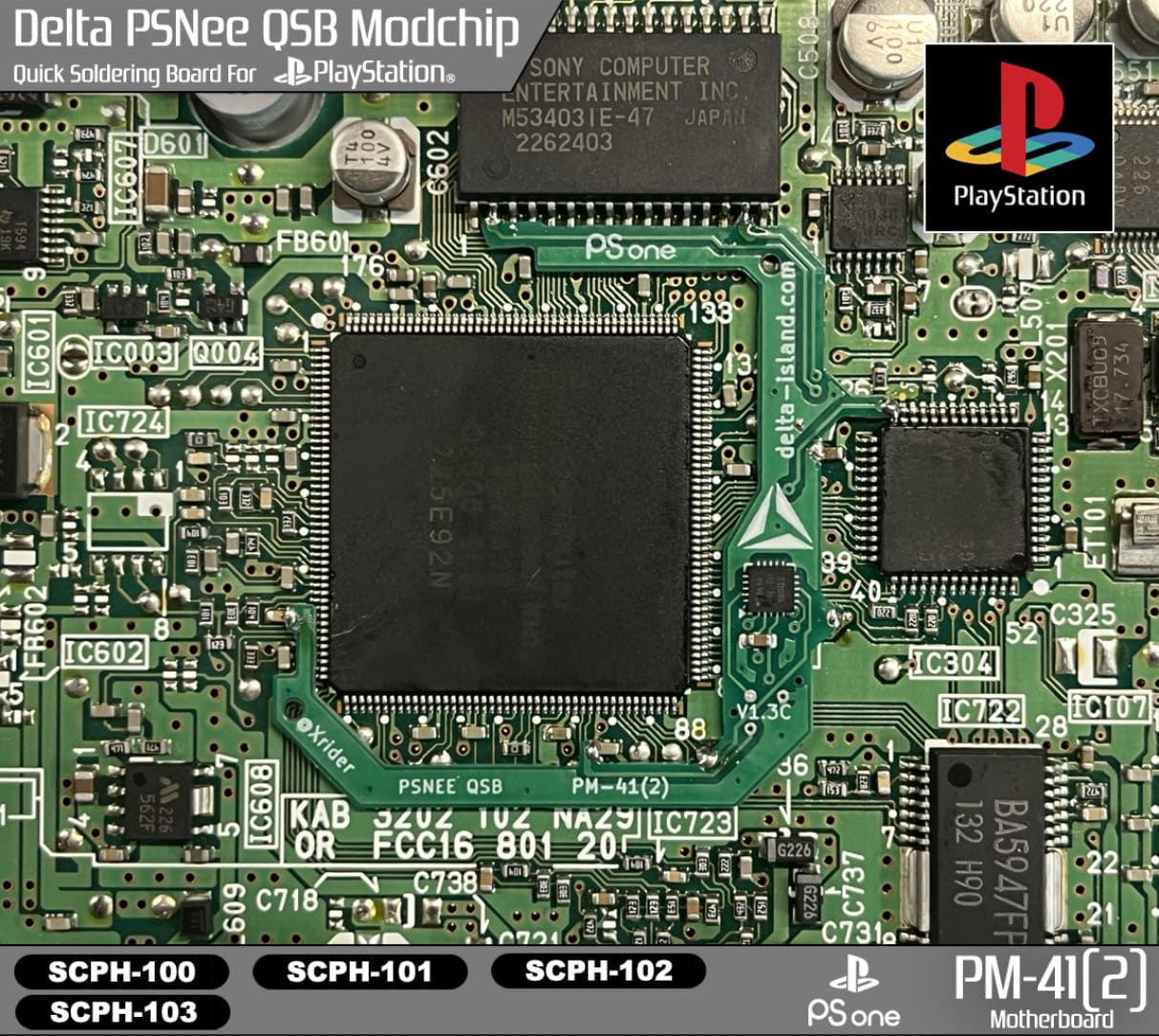
4.1.2 -Position your Delta SmartWave and proceed with soldering according to the following diagram:
For PU-7, an additional wire must be installed, running from the bottom side to the top side of the motherboard.


4.1.3 - Reassemble your console.
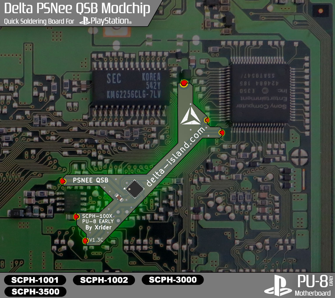
4.2 - PU-8 EARLY MainBoard
4.2.1 - Locate the resistors marked in red and remove them (top side).
Please note that depending on your motherboard version, you should have only one of the two resistors marked in red on the left.

4.2.2 - Position your Delta SmartWave and proceed with soldering according to the following diagram
For PU-8 EARLY, an additional wire must be installed, running from the bottom side to the top side of the motherboard.


4.2.3 - Reassemble your console.
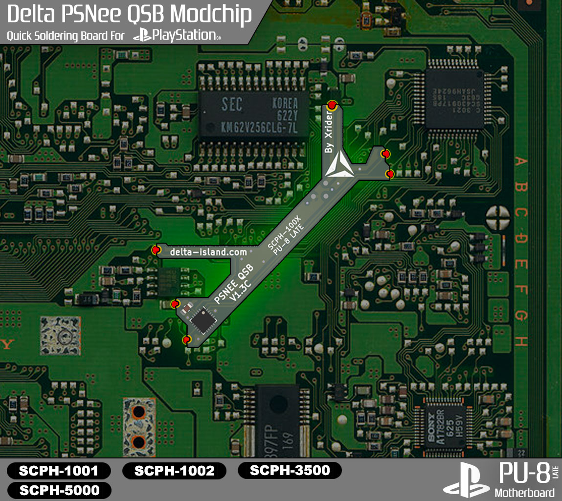
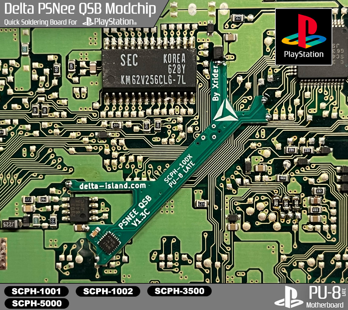
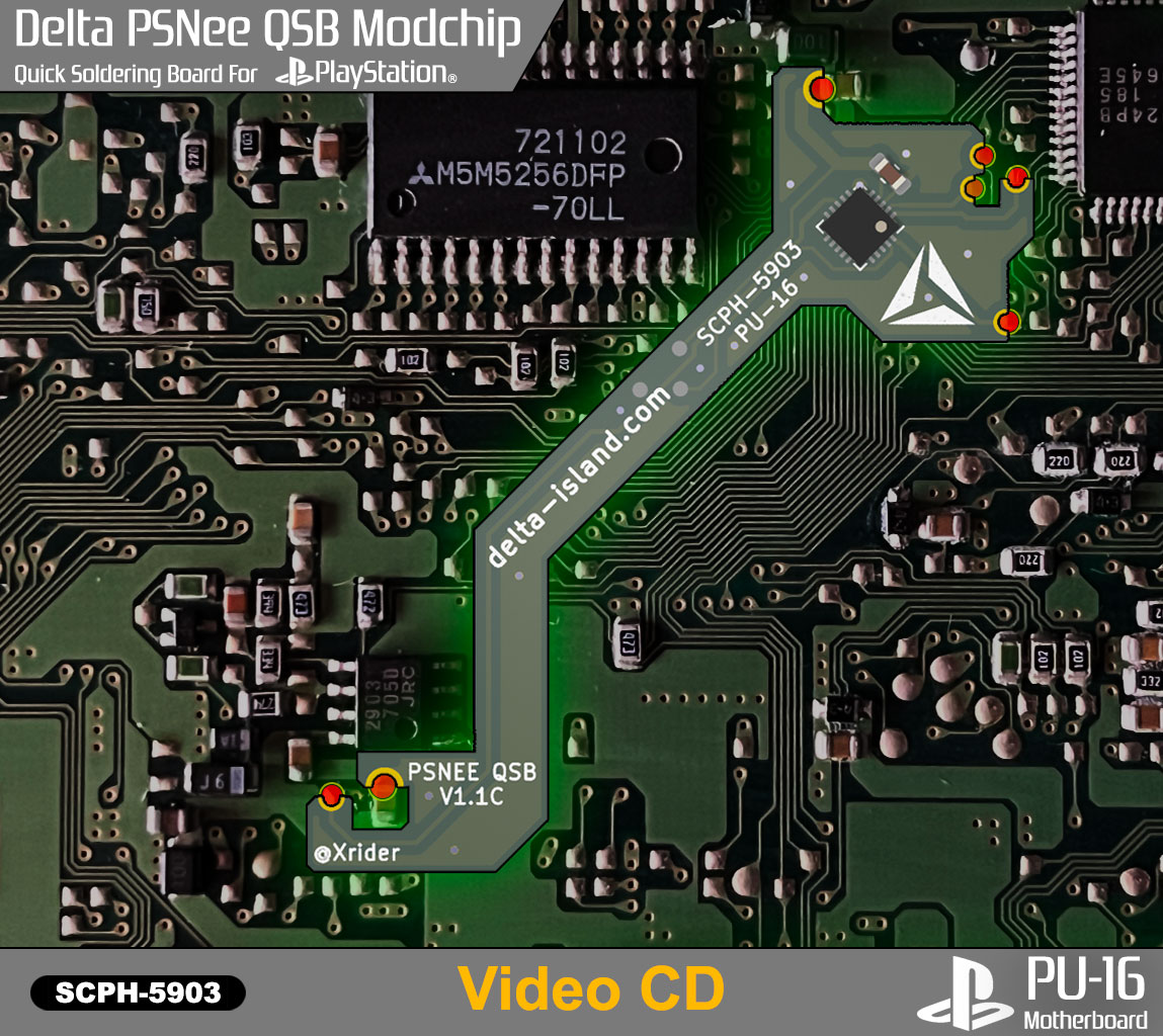
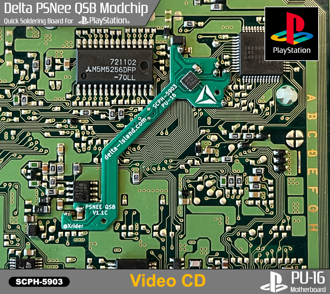
4.3 - PU-8 LATE & PU-16 Mainboard
4.3.1 - Locate the resistors marked in red and remove them (top side).
Please note that depending on your motherboard version, you should have only one of the two resistors marked in red.

4.3.2 - Locate the resistors marked in red and remove them (bottom side).
Please note that depending on your motherboard version, you should have only one of the two resistors marked in red.

4.3.3 - Position your Delta SmartWave and proceed with soldering according to the following diagram.


4.3.4 - Reassemble your console.
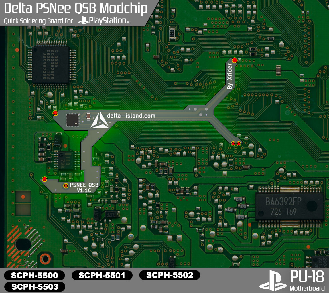
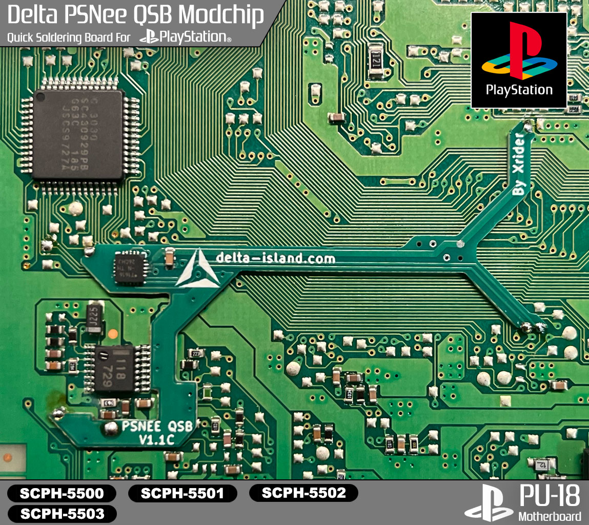
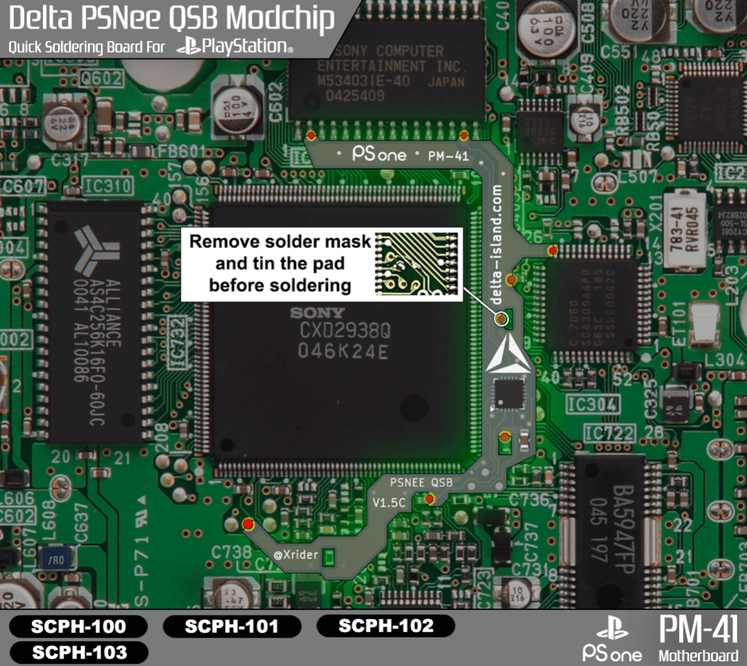
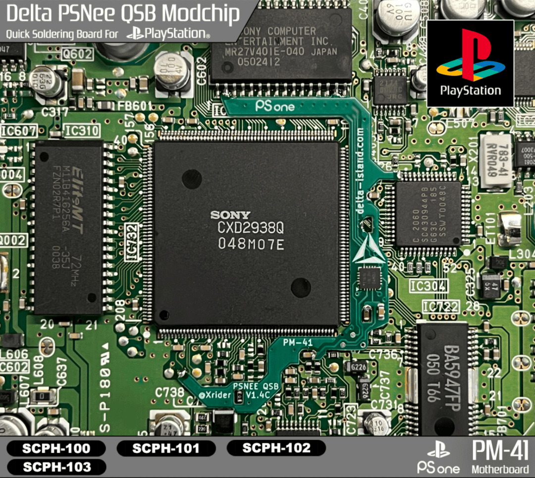
4.4 - PU-18 Mainboard
4.4.1 - Remove the upper metal shield from the motherboard using your soldering iron
4.4.2 - Locate the resistor marked in red on the top side of the motherboard and remove it.

4.4.3 - Position your Delta SmartWave on the bottom side of the motherboard and proceed with soldering according to the following diagram.


4.4.4 - Reinstall the upper metal shield on the motherboard using your soldering iron.
4.4.5 - Reassemble your console.
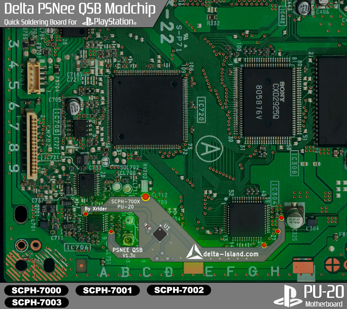
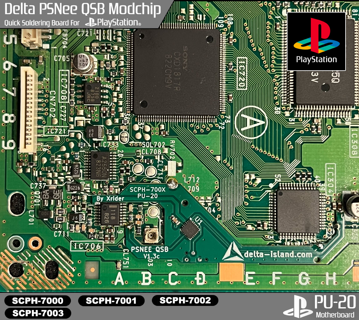
4.5 - PU-20 Mainboard
4.5.1 - Remove the upper metal shield from the motherboard using your soldering iron.
4.5.2 - Locate the two resistors marked in red and remove them.

4.5.3 - Position your Delta SmartWave and proceed with soldering according to the following diagram.


4.5.4 - Reinstall the upper metal shield on the motherboard using your soldering iron.
4.5.5 - Reassemble your console.
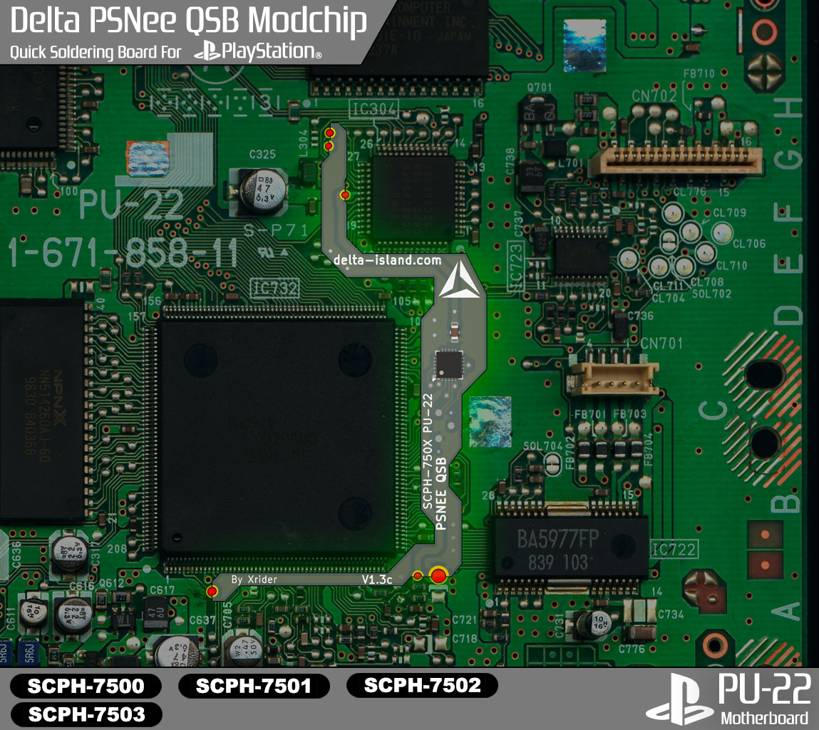
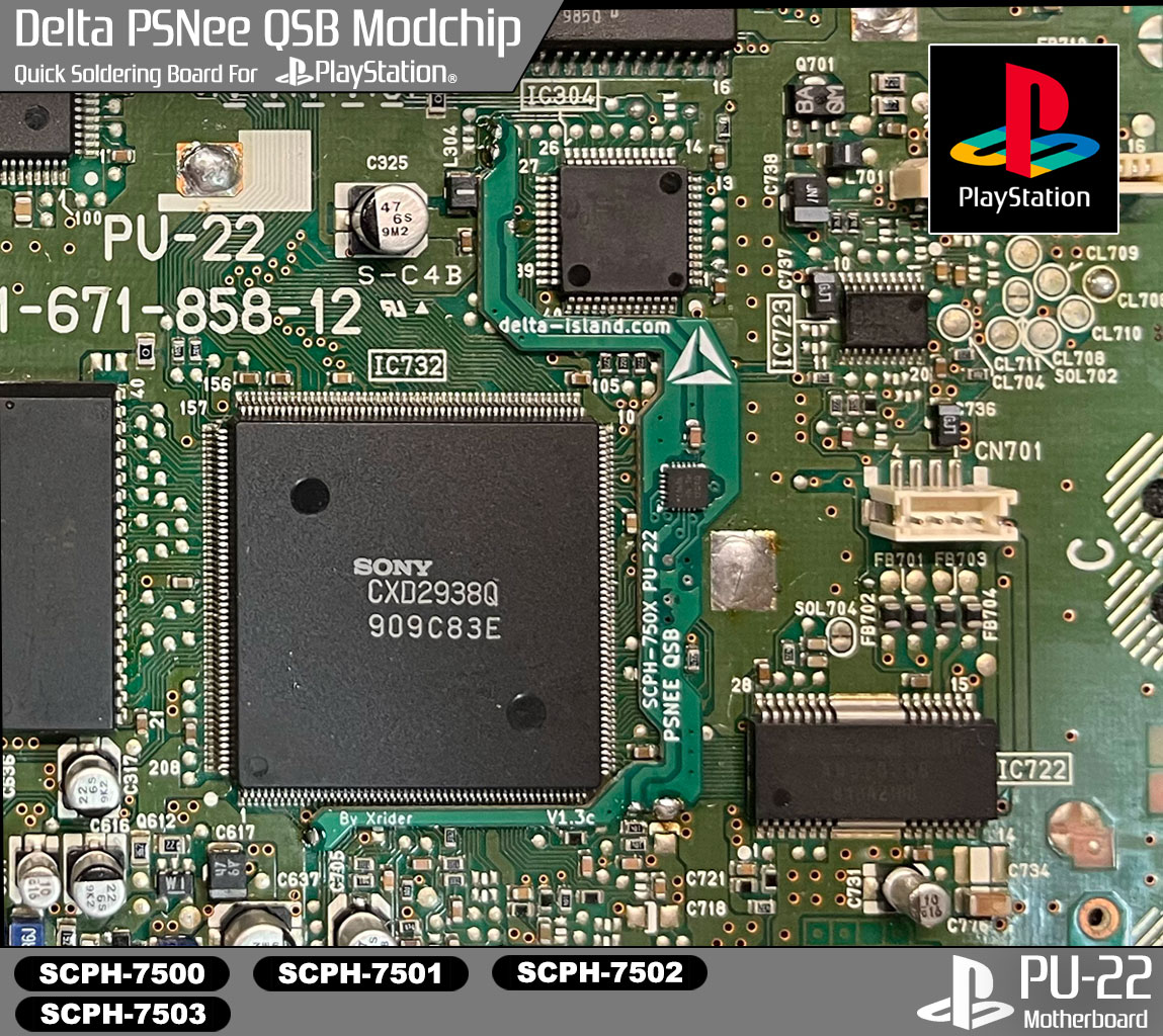
4.6 - PU-22 Mainboard
The PU-22 requires good soldering skills to ensure a proper and secure installation.
4.6.1 - Remove the upper metal shield from the motherboard using your soldering iron.4.6.2 - Locate the two resistors marked in red and remove them.

4.6.3 - Position your Delta SmartWave and proceed with soldering according to the following diagram.


4.6.4- Reassemble your console.
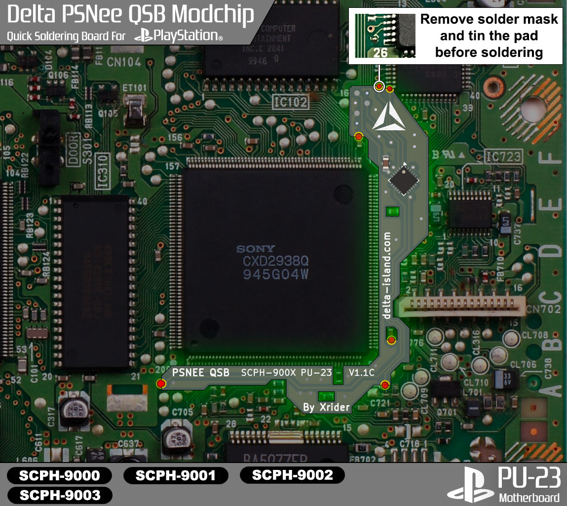
4.7 - PU-23 Mainboard
The PU-23 requires good soldering skills to ensure a proper and secure installation.
4.7.1 - Locate the resistor marked in red and remove it :

4.7.2 - Locate the two “VIA” points marked in red.
Using a scalpel, gently scrape the VIA points, then tin them with solder using your soldering iron :


4.7.3 - Locate pin 6 of the IC204 component and carefully lift it using a scalpel and a soldering iron :

4.7.4 - Position your Delta SmartWave and proceed with soldering according to the following diagram.


4.7.5 - Reassemble your console.
.jpg)