")
")
Tutorial • Dreamcast • GDEMU • Hardware
DreamTray – Installation Guide
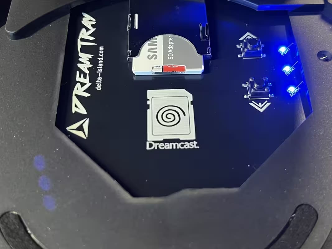
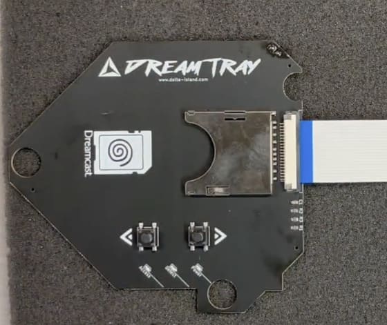
The DreamTray is an extension designed for your Sega Dreamcast equipped with a GDEMU. It fits into the empty bay left by the GD-ROM drive and allows you to relocate the SD card slot, secure handling, improve airflow, and add advanced features.
🌀 Restored airflow 💾 Relocated + secured SD ⬆️⬇️ UP/DOWN buttons 💡 LEDs (Power / Detect / Access)
Key points
🔧
Installation
Easy if you’ve already soldered before (2-pin header).
Easy if you’ve already soldered before (2-pin header).
🧊
Mandatory
Console powered off + capacitors fully discharged.
Console powered off + capacitors fully discharged.
🎮
Testing
Real-time button test via BIOS → Music.
Real-time button test via BIOS → Music.
Tip: if your images have different sizes, the layout stays clean thanks to object-fit:cover.
Why install a DreamTray?
After installing a GDEMU
- Large opening left by the missing GD-ROM drive
- Fragile GDEMU SD slot (depending on version)
- Risk of dropping the SD card inside the console
- Mechanical stress on the motherboard’s GD-ROM connector
- Limited disc switching (single button)
- Disrupted internal airflow
What DreamTray adds
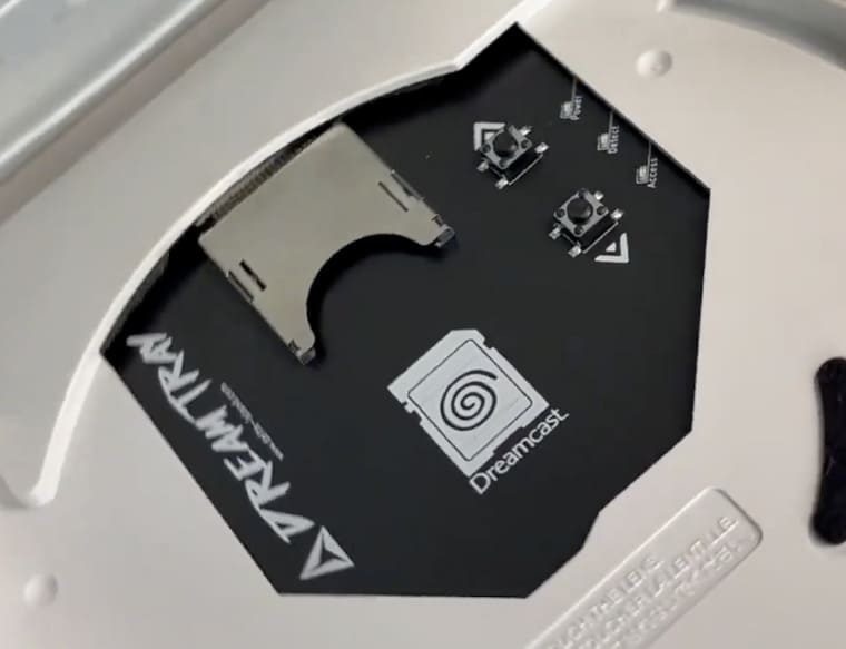
- Cleanly closes the GD-ROM opening
- Restores airflow closer to stock behavior
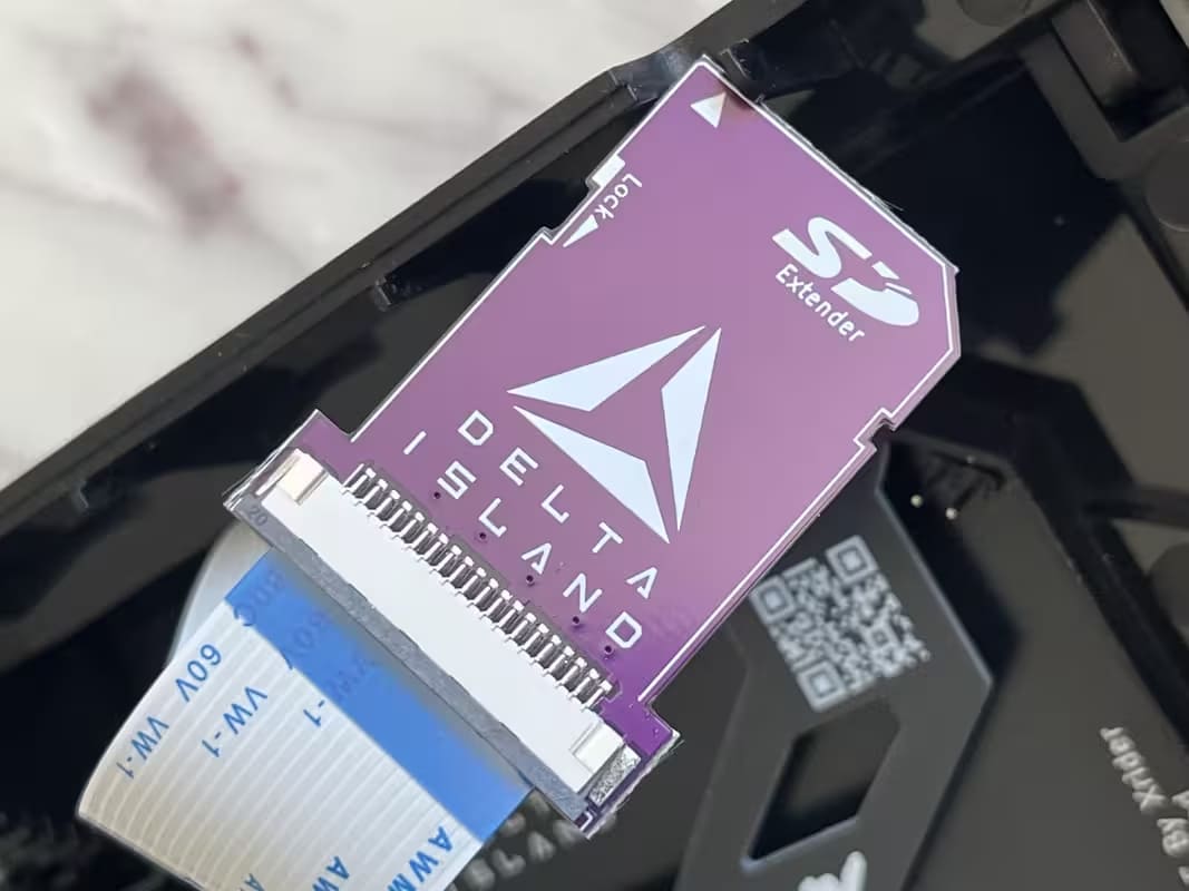
- Relocates the SD slot using a dedicated extension
- Adds two UP / DOWN buttons
- 3 LEDs: POWER, CARD DETECT, SD ACCESS
🛒 Available now: Delta DreamTray
Get the DreamTray from the Delta Store: a clean, durable solution to relocate and secure your SD card, restore airflow, and add UP/DOWN + status LEDs for a smoother GDEMU experience.
🔒 Important safety instructions
⚠️ POWER OFF is MANDATORY
• Completely unplug the console (power + cables).
• Wait several hours for capacitors to fully discharge.
• Never work on a powered console.
• Wait several hours for capacitors to fully discharge.
• Never work on a powered console.
Step-by-step installation
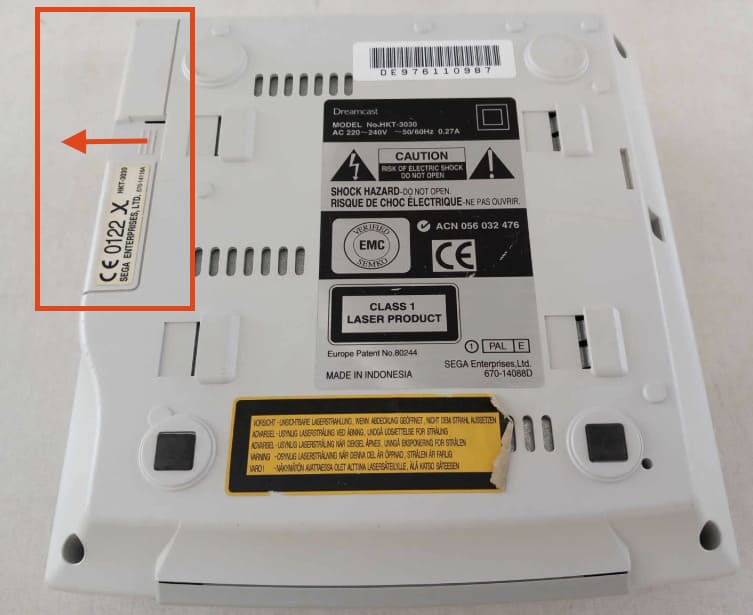
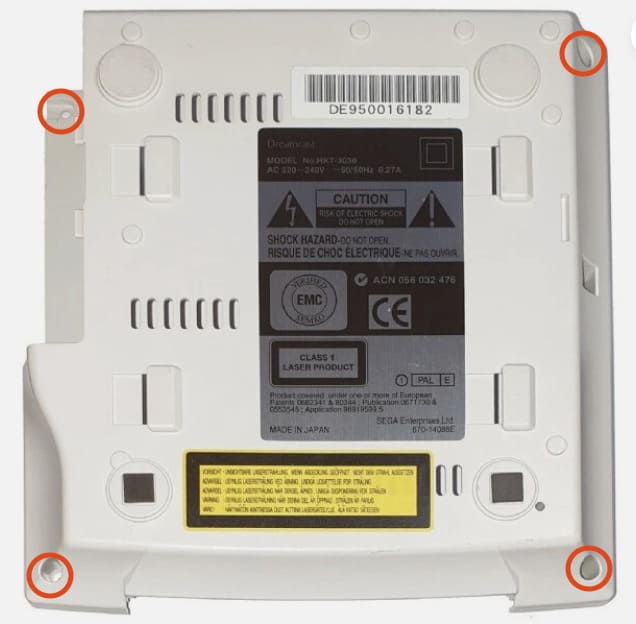
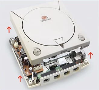
1 - Disassembling the Dreamcast
Goal: access the GD-ROM bay
• Remove the modem
• Remove the 4 bottom screws
• Lift the top shell
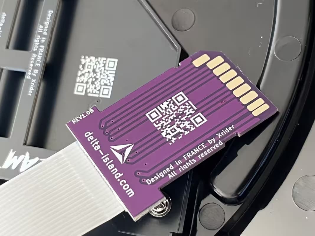
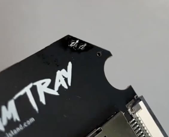
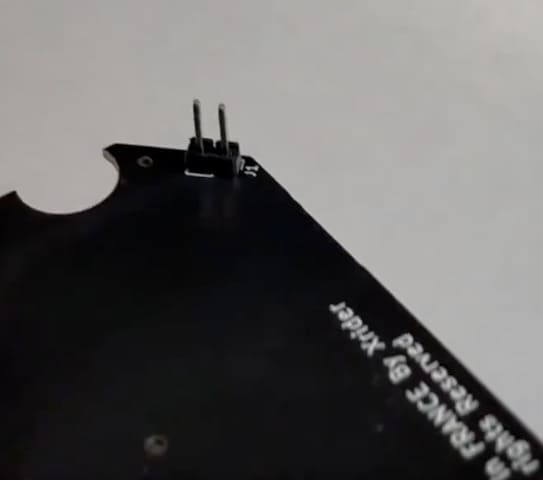
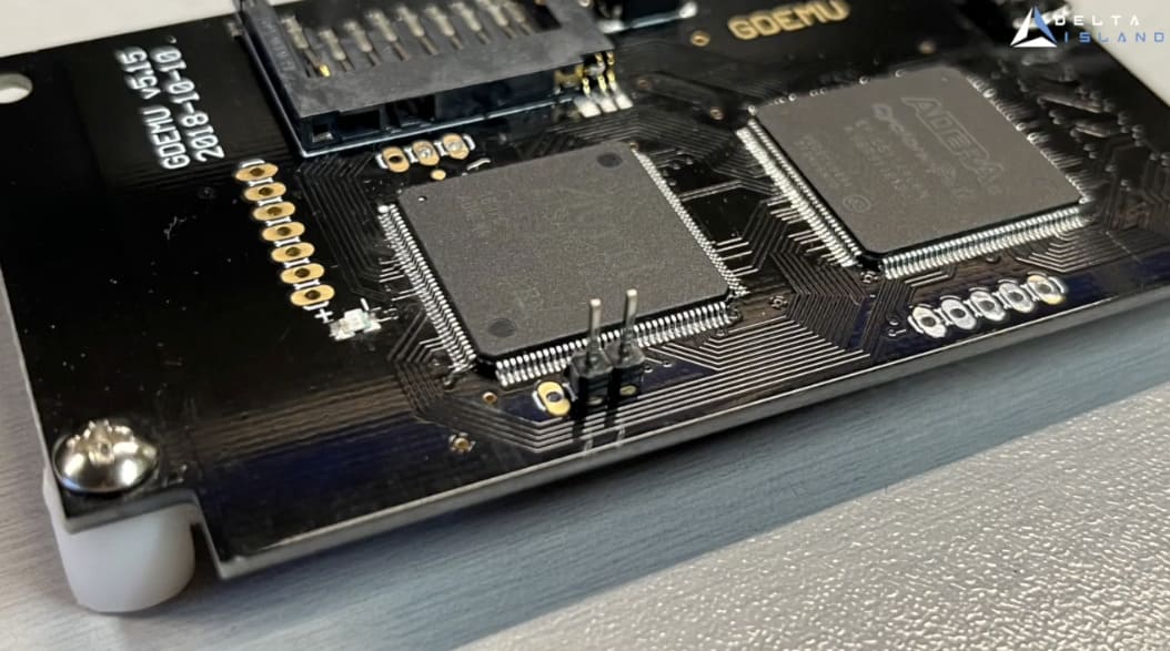
2 - PCB preparation
Goal: add the 2-pin headers
Note: solder joints must be clean. Inspect with a magnifier and avoid any solder bridges.
• 2-pin header on the DreamTray PCB
• 2-pin header on your GDEMU (not included)
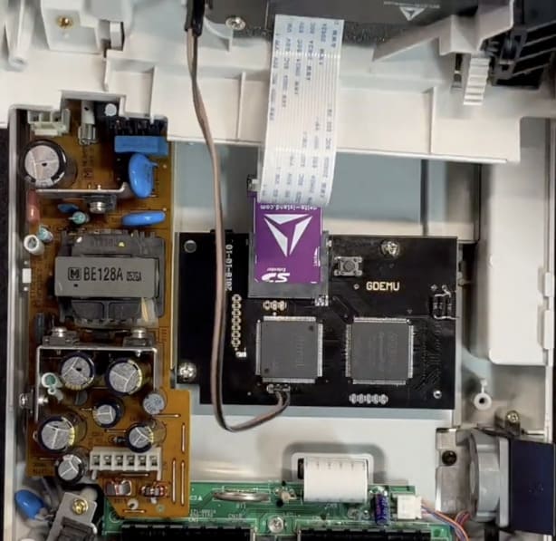
3 - Connections
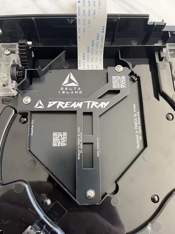
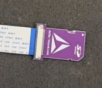
Ribbon cable + SD adapter
• Connect the ribbon cable to the DreamTray PCB
• Connect the SD extension
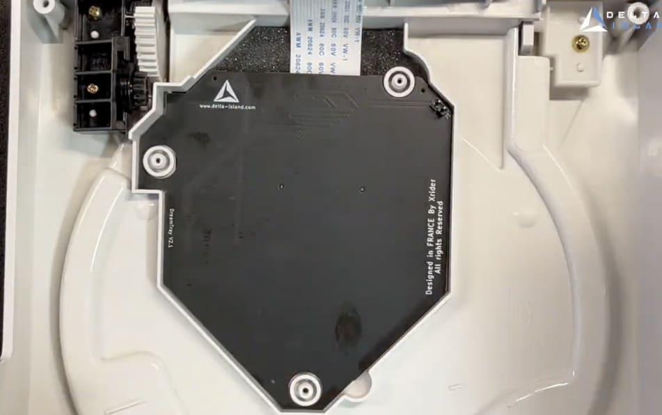
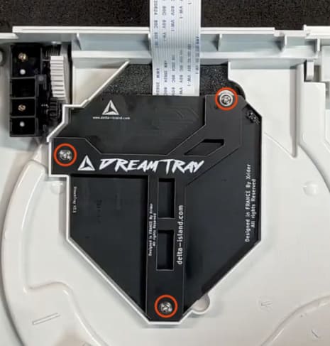
4 - Mounting
Positioning + bracket + screws
• Place the main PCB into the shell
• Add the retaining/support PCB
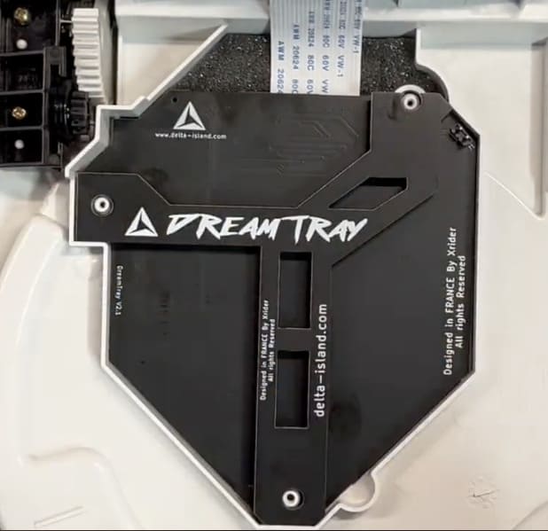
• Secure using the 3 included screws
5 - Reassembly
SD connection + Dupont cable + closing the console
Important: the included DreamTray ↔ GDEMU Dupont connection cable is required for the UP/DOWN buttons to work properly.
• Insert the SD adapter into the GDEMU
• Close the console and reinstall the screws
• Insert the SD card into the DreamTray
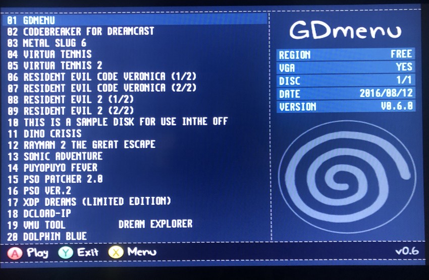
Testing the UP & DOWN buttons
The GDMENU software does not handle button inputs in real time (just like the original GDEMU button). To test the buttons with real-time feedback, use the Dreamcast BIOS.
Procedure
1) In GDMENU, press Y
2) Select EXIT TO SYSTEM MENU
3) BIOS → MUSIC
4) Test UP / DOWN (GDI/CDI scrolling)
1) In GDMENU, press Y
2) Select EXIT TO SYSTEM MENU
3) BIOS → MUSIC
4) Test UP / DOWN (GDI/CDI scrolling)
✅ The buttons remain 100% functional in-game.
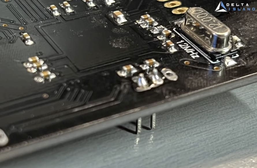
Diagnostics
If your GDEMU clone has SD detection issues, a small solder bridge may be required between two specific points. This fix improves reliability on SD sockets of variable quality.
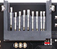
Thanks to vmicka for the tip.
🎥 Video tutorial
Link: https://www.youtube.com/watch?v=PXYupzitH1Y